Beschrijving


What Is a Worm and Wheel?
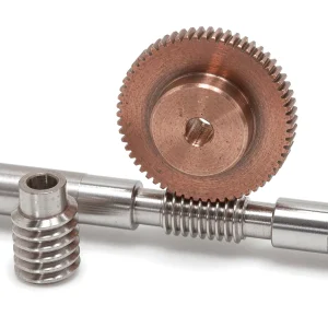
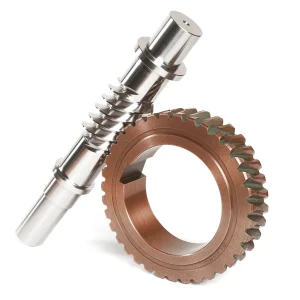
 A worm and wheel — also widely referred to as a worm gear set — is a mechanical transmission pairing composed of a worm (the driving screw-like shaft) and a worm wheel (the driven gear). These two components transfer both motion and power between two staggered shafts, with the angle between the shafts typically set at 90 degrees. The worm resembles a threaded bolt in profile, while the worm wheel shares visual similarities with a helical spur gear, though its tooth form is carefully shaped to achieve line contact rather than point contact with the worm.
During operation, the worm wheel teeth slide and roll along the spiral surface of the worm. To maximise the contact area and improve load distribution, the worm wheel is formed into a concave arc shape along its tooth width direction — partially wrapping around the worm. This design transforms point contact into line contact, dramatically increasing the load-bearing capacity and service life of the assembly. For UK engineers and procurement teams sourcing industrial-grade worm and wheel sets, this line-contact characteristic is a critical differentiator from simpler staggered shaft helical gear arrangements.
One of the most valued properties of the worm gear set is its ability to deliver very large gear reduction ratios within a compact envelope. Standard worm and wheel transmission ratios commonly reach 20:1, and in demanding applications, ratios of 300:1 or higher are achievable. Many worm drive configurations also provide inherent self-locking — when the lead angle of the worm is smaller than the equivalent friction angle, the worm wheel cannot back-drive the worm. This characteristic is widely exploited in lifting equipment, safety interlocks, and positioning systems across UK manufacturing facilities.
Technical Specifications
Working Principle & Proper Meshing Conditions

Understanding how a worm and wheel meshes correctly is fundamental to specifying the right set for any power transmission project. Two key parameters govern proper meshing. The module and pressure angle of the worm and the worm wheel in the middle plane must be equal — meaning the end module of the worm wheel equals the axial surface module of the worm, and both must be at their standard values. Similarly, the end pressure angle of the worm wheel must equal the axial pressure angle of the worm.
When the stagger angle is specified, it must be strictly maintained, and both the worm and the worm wheel must share the same helical direction. Getting these parameters right from the outset avoids premature wear, heat build-up, and vibration — three of the most common failure modes reported by UK maintenance engineers working with incorrectly specified worm drive assemblies.
Material Selection for Worm and Wheel
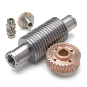
Selecting the correct material pairing for a worm and wheel set has a direct bearing on operating temperature, wear rate, noise level, and total cost of ownership. Ever Power offers a broad range of material options to match every duty — from light-duty automation to continuous heavy industrial cycles. Worm wheels are typically produced from cast tin bronze or aluminium iron bronze, with cast iron reserved for low-speed, non-critical transmissions. The worm itself is most commonly manufactured from hardened alloy steel or C45 steel, ensuring the hardness differential necessary for controlled wear on the softer wheel teeth rather than on the worm.
Worm and Wheel — Key Performance Features
The engineering advantages of the worm and wheel transmission make it a preferred choice wherever large speed reduction, compactness, low noise, or positional holding is required. UK procurement specialists evaluating gear set suppliers should weigh these characteristics carefully when comparing options.
High Transmission Ratio in Compact Space
Worm and wheel sets deliver large transmission ratios — commonly 20:1, and up to 300:1 or higher — within a smaller footprint than staggered shaft helical gear arrangements. This compactness is particularly valuable in UK machine tool and automation applications where cabinet space is at a premium.
High Load-Bearing Capacity via Line Contact
Because the meshing tooth surfaces engage in line contact, the worm and wheel pair carries significantly higher loads compared to point-contact alternatives. This is crucial for heavy-duty industrial machinery and material handling equipment operating under sustained high torque conditions.
Smooth, Low-Noise Multi-Tooth Drive
Worm transmission operates as a multi-tooth meshing drive, comparable in its smoothness to helical drive. Multiple teeth share the load simultaneously, reducing noise and vibration to levels well-suited for environments where quiet operation is required — from hospital equipment to precision measuring instruments.
Reverse Self-Locking Safety
When the worm lead angle is smaller than the equivalent friction angle between meshing teeth, the assembly becomes self-locking — the worm wheel cannot reverse-drive the worm. This built-in safety characteristic is widely used in lifting machinery and heavy load positioning systems to prevent uncontrolled back-drive under power loss.
Design Consideration: Efficiency & Heat
The relative sliding velocity between meshing surfaces generates friction losses, reducing transmission efficiency and producing heat. This makes lubrication and material selection especially important. Ever Power addresses this by offering bronze alloy wheel options with proven anti-friction characteristics, together with guidance on lubrication system design for high-duty-cycle installations.
Large Axial Force Management
Worm drives generate significant axial forces on the worm shaft, requiring properly specified thrust bearings. Ever Power’s engineering support team assists UK clients in selecting matched bearing arrangements and housing configurations, ensuring long-term reliability without unexpected shaft deflection or premature bearing failure.
Application Scenarios
From semiconductor fabs to solar tracking systems, the worm and wheel set appears wherever controlled, high-ratio speed reduction in a compact form is required. UK industries spanning automotive, food production, logistics, and aerospace all rely on precision worm gear sets. Typical applications supplied by Ever Power include:
Our Manufacturing Facility & Custom Service

Ever Power operates a fully equipped manufacturing facility dedicated to precision worm gear production. Our workshops house multi-axis CNC gear hobbing machines, CNC grinding centres, and coordinate measuring equipment that together allow us to manufacture worm and wheel sets to DIN6 through DIN9 tolerances with repeatability in the 0.001 mm range. Whether your project calls for a standard metric module set or a highly specific non-standard configuration, our production team has the tooling and material stock to respond quickly — with sample lead times of 20 business days and bulk orders completed in 25 days.
Custom worm and wheel manufacturing is a core strength of Ever Power. We work directly with UK design engineers and procurement teams to produce bespoke gear sets from engineering drawings, CAD files, or even reverse-engineered samples. Custom specifications we regularly accommodate include non-standard modules, special pressure angles, oversized worm wheels for high-torque applications, special surface coatings for corrosive environments, and material combinations not available in standard catalogues. Our team can also advise on optimal helix angle and lead angle selection to tune the self-locking characteristic for your specific operating conditions.
Customer Success Story
UK Automated Packaging Line — West Midlands
Industry: Food Processing & Packaging | Location: West Midlands, England | Application: Conveyor indexing drives
 A mid-size food packaging manufacturer in the West Midlands was experiencing premature failure of worm gear sets on its high-speed case erecting lines — a recurring problem traced to poor material selection and inadequate surface hardness on the worm shaft. After contacting Ever Power, our engineering team reviewed their duty cycle and shaft centre distances, recommending a cast tin bronze worm wheel paired with a C45 hardened steel worm in M5 module, DIN7 precision grade with nickel-plated surface treatment for moisture resistance.
Following installation of the replacement worm and wheel sets, the customer reported zero gear failures over an 18-month production run — compared to quarterly replacement costs with their previous supplier. Ongoing supply is now managed on an annual blanket order with 25-day replenishment lead times, keeping downtime risk negligible for their three-shift operation.
What Our Customers Say
“We specified a non-standard module worm and wheel for a bespoke indexing table project. Ever Power produced exactly what our drawings required, within tolerance, on time. Their technical support during the design stage saved us weeks of back-and-forth.”
“Price was competitive and the quality of the bronze worm wheels genuinely impressed our inspection team. Dimensions matched the drawings spot on. We have now placed our third repeat order and lead times have been consistent every time.”
“We needed stainless steel worm gear sets for a food-grade conveyor — not something every supplier can do. Ever Power handled the whole specification process and delivered samples within three weeks. The finish quality was excellent and they passed our hygiene compliance checks without issue.”
Frequently Asked Questions
Tell us your module, material, reduction ratio, and quantity — and we will turn a technical quote around within one working day. Custom specifications, sample orders, and reverse engineering all welcome.
edit by gzl